LCD液晶が新しくなっていたので使ってみました。
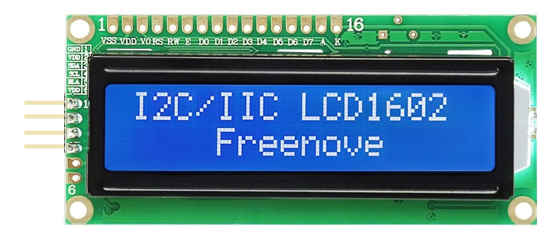
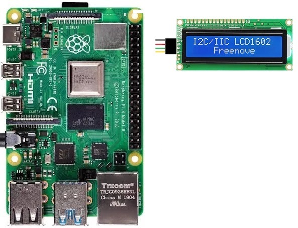
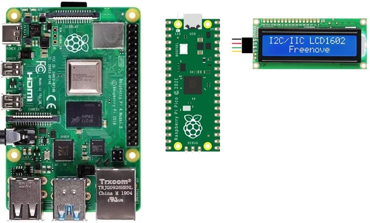
液晶はこんな感じのもの。
2行16文字表示(16 x 2)
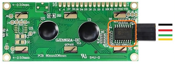
以前は表示用の回路は別になっていて半田付けする必要がありました。
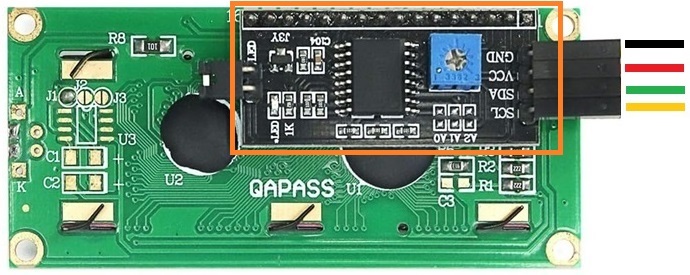
新しいタイプは回路が最初からLCDボード上に載ってます。
2つのプラットフォームで使ってみます。
ラズパイ4Model B
OSはBullseye Desktop 64-bit
Raspberry Pi の設定でインターフェースのI2Cを有効にしておきます。
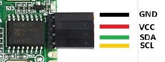
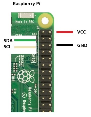
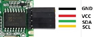
GPIOの結線はこんな感じ。電源電圧には5Vを使います。
モジュールファイルに以下を追加。
|
1 |
sudo nano /etc/modules |
i2c-bcm2708
i2c-dev
I2Cに必要なライブラリをインストール
|
1 |
sudo apt-get install -y python3-smbus i2c-tools |
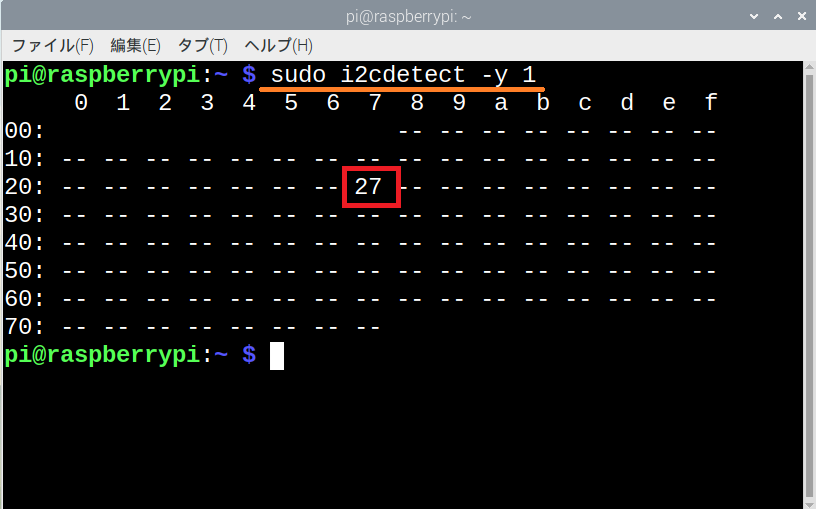
ディスプレイの接続とI2C通信のアドレスを確認
|
1 |
sudo i2cdetect -y 1 |
アドレスが「0x27」の場合は以下のファイルをダウンロード
wget http://osoyoo.com/driver/i2clcda.py
アドレスが「0x3f」の場合は
wget http://osoyoo.com/driver/i2clcdb.py
ディスプレイに文字を表示させてみる
|
1 |
sudo python3 i2clcda.py |
Created by
Osoyoo.com
とか表示されればOK。
【i2clcda.py】
|
1 2 3 4 5 6 7 8 9 10 11 12 13 14 15 16 17 18 19 20 21 22 23 24 25 26 27 28 29 30 31 32 33 34 35 36 37 38 39 40 41 42 43 44 45 46 47 48 49 50 51 52 53 54 55 56 57 58 59 60 61 62 63 64 65 66 67 68 69 70 71 72 73 74 75 76 77 78 79 80 81 82 83 84 85 86 87 88 89 90 91 92 93 94 95 96 97 98 99 100 101 102 103 104 105 106 107 108 109 |
# _____ _____ _____ __ __ _____ _____ #| | __| | | | | | #| | |__ | | |_ _| | | | | #|_____|_____|_____| |_| |_____|_____| # # Project Tutorial Url:http://osoyoo.com/?p=1031 # import smbus import time # Define some device parameters I2C_ADDR = 0x27 # I2C device address, if any error, change this address to 0x3f LCD_WIDTH = 16 # Maximum characters per line # Define some device constants LCD_CHR = 1 # Mode - Sending data LCD_CMD = 0 # Mode - Sending command LCD_LINE_1 = 0x80 # LCD RAM address for the 1st line LCD_LINE_2 = 0xC0 # LCD RAM address for the 2nd line LCD_LINE_3 = 0x94 # LCD RAM address for the 3rd line LCD_LINE_4 = 0xD4 # LCD RAM address for the 4th line LCD_BACKLIGHT = 0x08 # On #LCD_BACKLIGHT = 0x00 # Off ENABLE = 0b00000100 # Enable bit # Timing constants E_PULSE = 0.0005 E_DELAY = 0.0005 #Open I2C interface #bus = smbus.SMBus(0) # Rev 1 Pi uses 0 bus = smbus.SMBus(1) # Rev 2 Pi uses 1 def lcd_init(): # Initialise display lcd_byte(0x33,LCD_CMD) # 110011 Initialise lcd_byte(0x32,LCD_CMD) # 110010 Initialise lcd_byte(0x06,LCD_CMD) # 000110 Cursor move direction lcd_byte(0x0C,LCD_CMD) # 001100 Display On,Cursor Off, Blink Off lcd_byte(0x28,LCD_CMD) # 101000 Data length, number of lines, font size lcd_byte(0x01,LCD_CMD) # 000001 Clear display time.sleep(E_DELAY) def lcd_byte(bits, mode): # Send byte to data pins # bits = the data # mode = 1 for data # 0 for command bits_high = mode | (bits & 0xF0) | LCD_BACKLIGHT bits_low = mode | ((bits<<4) & 0xF0) | LCD_BACKLIGHT # High bits bus.write_byte(I2C_ADDR, bits_high) lcd_toggle_enable(bits_high) # Low bits bus.write_byte(I2C_ADDR, bits_low) lcd_toggle_enable(bits_low) def lcd_toggle_enable(bits): # Toggle enable time.sleep(E_DELAY) bus.write_byte(I2C_ADDR, (bits | ENABLE)) time.sleep(E_PULSE) bus.write_byte(I2C_ADDR,(bits & ~ENABLE)) time.sleep(E_DELAY) def lcd_string(message,line): # Send string to display message = message.ljust(LCD_WIDTH," ") lcd_byte(line, LCD_CMD) for i in range(LCD_WIDTH): lcd_byte(ord(message[i]),LCD_CHR) def main(): # Main program block # Initialise display lcd_init() while True: # Send some test lcd_string("Created by <",LCD_LINE_1) lcd_string("Osoyoo.com <",LCD_LINE_2) time.sleep(3) # Send some more text lcd_string("> Tutorial Url:",LCD_LINE_1) lcd_string("> http://osoyoo.com",LCD_LINE_2) time.sleep(3) if __name__ == '__main__': try: main() except KeyboardInterrupt: pass finally: lcd_byte(0x01, LCD_CMD) |
Pico
開発用母艦は上記と同じラズパイ4を使います。
PicoからI2C LCDスクリーンに情報を送信して表示します。
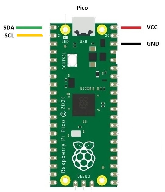
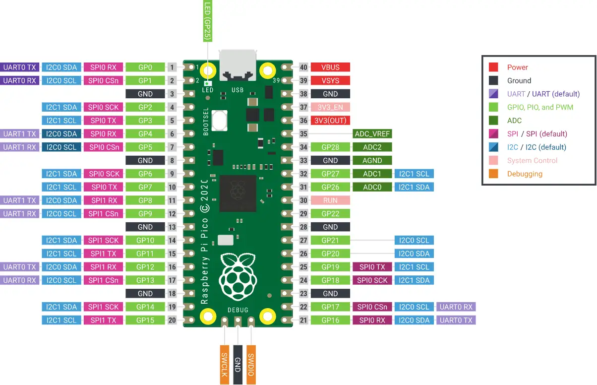
典型的なI2Cスレーブデバイスには、データピン(SDA)とクロックピン(SCL)が必要で、これらはRaspberry Pi PicoのSDAとSCLピンに接続する必要があります。
GPIOの結線はこんな感じ。電源電圧には5Vを使います。
開発環境はラズパイにデフォルトで準備されているThonny IDE (Python)を使います。
OSOYOOのサイトからLCDにアクセスするための2つのPythonライブラリ(lcd_apiとpico_i2c_lcd)をダウンロードしておきます。
ファイルを解凍して、lcd_api.pyとpico_i2c_lcd.pyの2つのファイルを保存。
Picoのファームウェアもダウンロードしておきます。
PicoのBOOTSEL ボタンを押しながらUSBケーブルでラズパイに接続してファームウェアをドラグ・ドロップ。Pico は再起動します。
開発環境のThonny起動
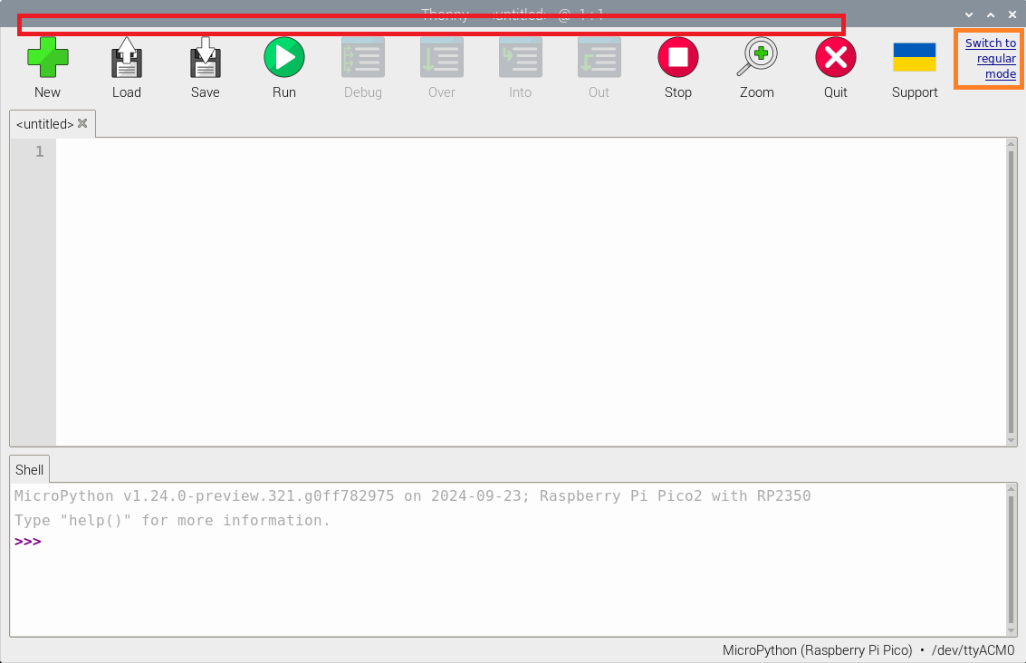
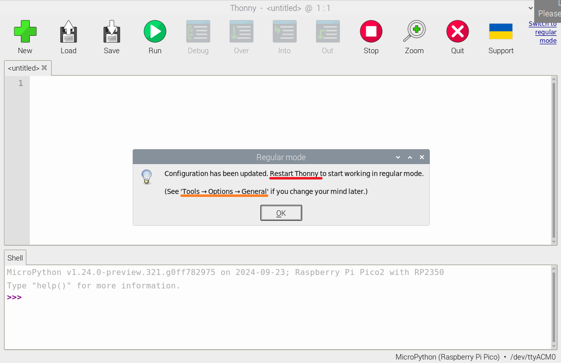
Thonny はデフォルトではメニュが何も表示されていません。このままでは使いずらいので表示しておきます。右端にあるSwitch to regulear mode をクリックします。
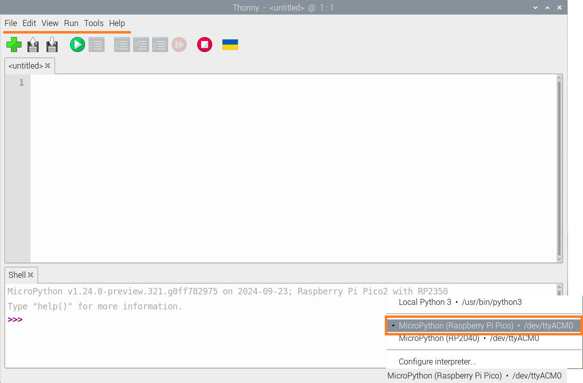
Thonny を再起動します(もう一度非表示にする場合はTool ->Options->UI mode->simpleを選んで再起動します)。
こんな感じ。右下のメニュでRaspberry Pi Pico のMicroPython環境に接続しているのを確認。
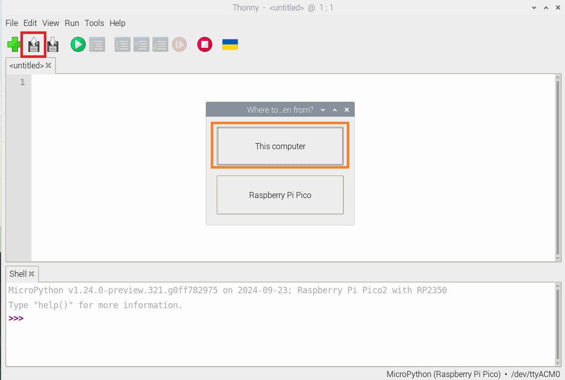
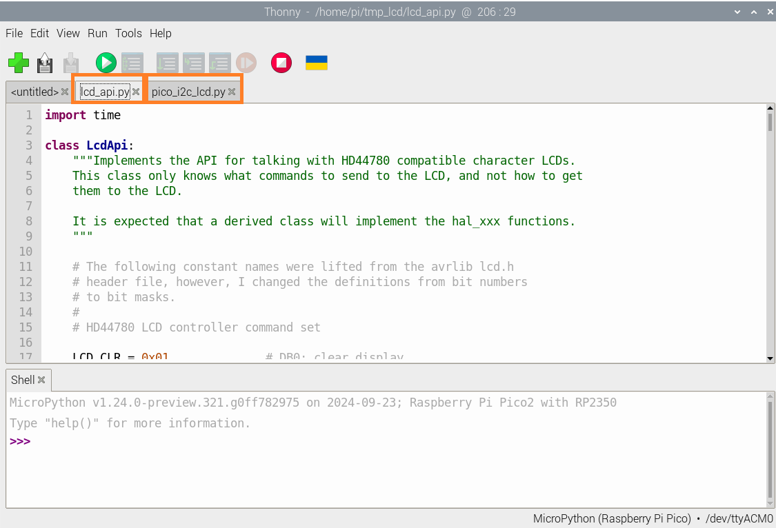
Openメニュで上記で保存しておいたlcd_api.pyとpico_i2c_lcd.pyの2つのファイルを読み込みます。
こんな感じ。
この2つのコードを同じファイル名でPicoのトップディレクトリに保存します。
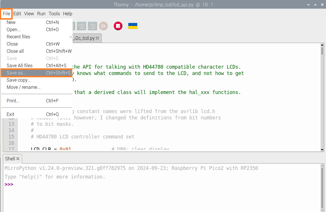
File ー>Save as … で実行
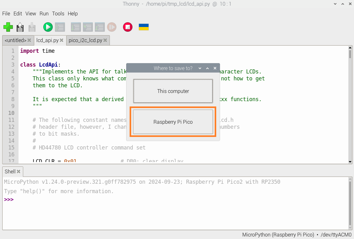
Pico に保存します。
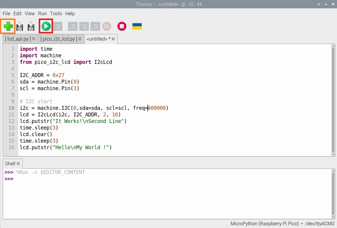
新しいコードを書き込んで実行します。
I2C_ADDRについて、
machine.I2C でscan()を実行して取得したものを使います。
print(hex(i2c.scan()[0]),’ (hex)’)
|
1 2 3 4 5 6 7 8 9 10 11 12 13 14 15 16 |
import time import machine from pico_i2c_lcd import I2cLcd I2C_ADDR = 0x27 sda = machine.Pin(0) scl = machine.Pin(1) # I2C start i2c = machine.I2C(0,sda=sda, scl=scl, freq=400000) lcd = I2cLcd(i2c, I2C_ADDR, 2, 16) lcd.putstr("It Works!\nSecond Line") time.sleep(3) lcd.clear() time.sleep(3) lcd.putstr("Hello\nMy World !") |
Hello
My World !
と表示されればOK。
Appendix
有機液晶ディスプレイ(OLED)はこちら
Pi Pico (W)で有機ELディスプレイに日本語表示(メモ)
Appendix2
Leave a Reply