
2輪走行ロボットを自作してみます。
で、その前にシミュレータを使ってどんな動きになるのか見てみます。
*FireFoxだと動画が見えないかもしれません、ChromeかEdgeをお使いください。
2輪走行ロボットの基本形はTurtleBot3のようです。TurtleBot3には2つの型があります。
こんな感じ。
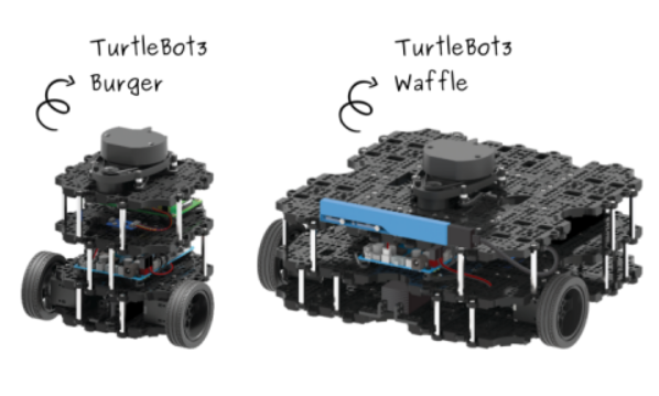
ここではwaffleに似た2輪走行ロボットを想定します。名前はmy_robotにしときます。サイズはBot3よりやや小さめ。
はじめに
シミュレーション用ロボットの作成にはurdf、xacroファイルを使います。いろいろな記述の仕方があるようですが、ROBOTISのシミュレーションパッケージの以下のディレクトリにあるファイルを参考にします。(シミュレーションパッケージのインストールは4/5でやります)
/opt/ros/melodic/share/turtlebot3_description/urdf
参照するファイルは以下の3つで、2つ改名して使います。変更した各ファイルについては下記参照。
common_properties.xacro
turtlebot3_waffle.gazebo.xacro ー> my_robot.gazebo.xacro
turtlebot3_waffle.urdf.xacro ー> my_robot.urdf.xacro
urdfやxacroについてはここのサイトを参照。
作成するxacroはオリジナルとは違っている部分が多いですが、自分のロボット用に変更しながら試しています。
● common_properties.xacro
定数や変数、標準形状のイナーシャ (慣性モーメント) の計算式などを記述。
オリジナルには突然1.57という数字が現れて「なんのこと?」という感じになりますが、要は π/2 ということです。
ちなみに、標準形状じゃない場合のイナーシャの計算はInertial parameters of triangle meshesを参照。
● my_roboto.gazebo.xacro
パーツのGazeboへのrefrenceや、車輪やカメラ・LiDARなどを制御するPluginを記述
● my_robot.urdf.xacro
common_properties.xacroとmy_roboto.gazebo.xacroを読み込み、各種ロボットのパーツを統合します。
独自モデルでは、形をシンプルにしたいので標準形状であるboxやcylinder、sphereを使います。
LiDARやカメラはオリジナルにあるとおりのメッシュ(Triangle Mesh)ファイルを使ってみます。
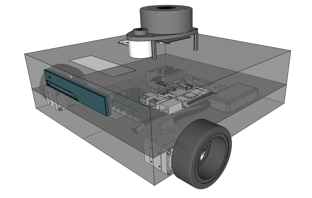
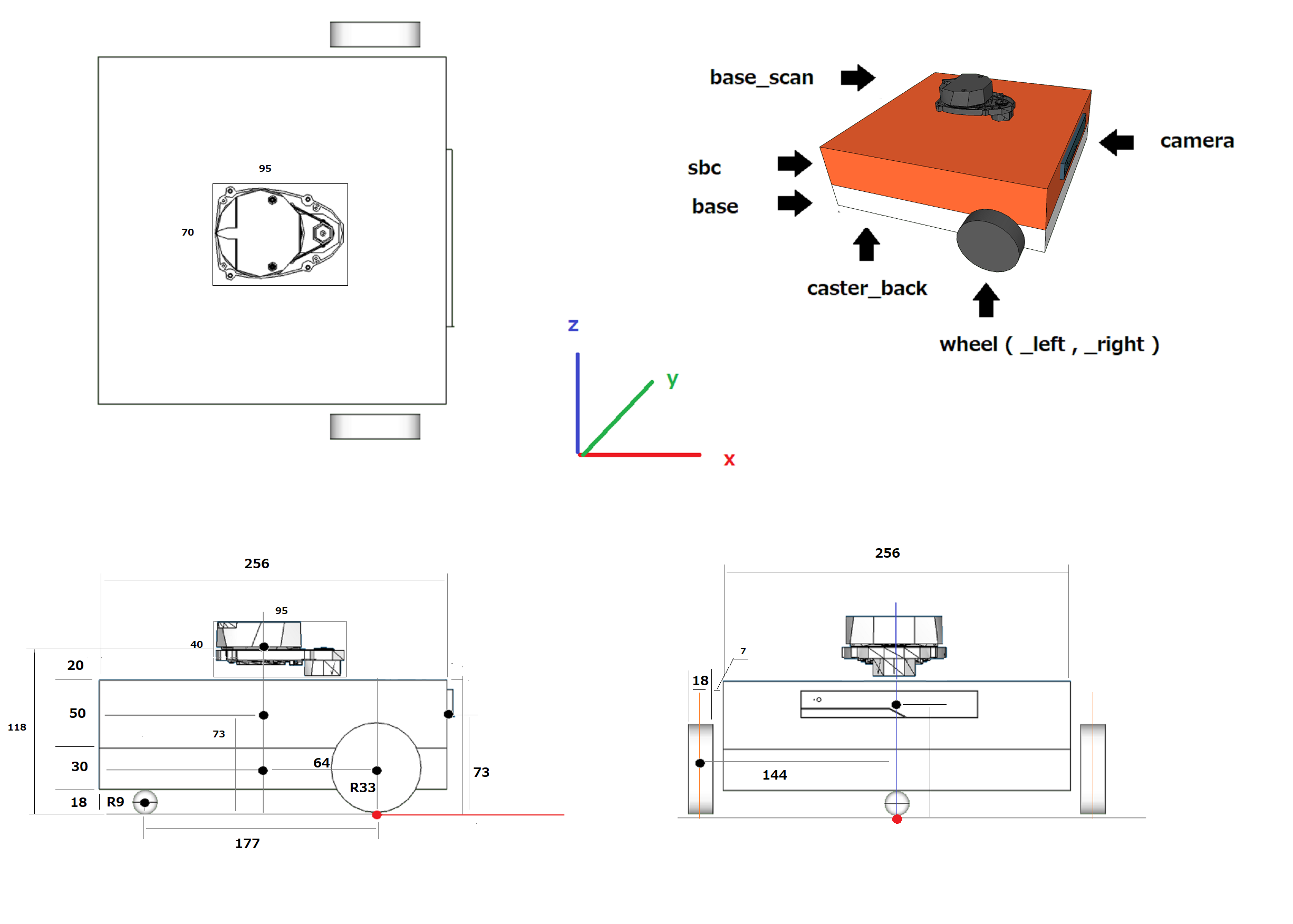
こういうロボットです。
base_scan : lds (LiDAR) レーザー測距センサー
sbc : single board computer (Raspberry Pi / Jetson Nano) 制御用シングルボードコンピュータ
base : Dynamixel Moter , OpenCR , LIPO Battery , … モーター、マイコンボード、バッテリー…
caster_back : 後部のボール型補助輪
wheel : 車輪
各パーツの位置は車軸中心の床への投影面:base_footprint(赤丸)からパーツの重心への相対距離で取っています。
使用するプラットフォームはJetson Nano (Jetpack 4.6)
ROSはMelodic Morenia
環境構築に関しては以下をご参照ください。
Jetson Nano にROS1 (Melodic) をインストール(メモ)
事前準備
urdfに矛盾がないかチェックするツールやキーボードからPlugin経由でGazeboに表示されたロボットを制御するパッケージをインストールしておきます。
|
1 2 3 |
sudo apt install liburdfdom-tools sudo apt install ros-melodic-teleop-twist-keyboard |
では、パッケージの作成から開始します。
ワークスペースにmy_robotパッケージを作成
依存パッケージはurdf、xacroの2つ。
|
1 2 3 4 5 6 7 |
cd ~/catkin_ws/src catkin_create_pkg my_robot urdf xacro cd my_robot mkdir urdf worlds launch config meshes |
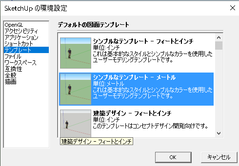
LiDARモデルとカメラ(RealSense R200)はメッシュファイルを使います。ファイル形式はstlかdaeです。Wisteriahillは伝統的(?)に3D CADはSketchUpを使っているのでdae形式がメインです。SketchUpはBlenderやFusion360と同様に右手座標系のCADですので、作った形状はそのままexportしてurdfで使えます。ちなみに、UnityやUnreal Engine は左手です。
また、urdfは国際単位系なので作業する場合、メートル単位を使います。
SketchUpの場合
メッシュファイルは以下からダウンロードできます。
このlds(LiDAR)とR200を以下のフォルダーにコピーしておきます。
~/catkin_ws/src/my_robot/meshes
urdfディレクトリへ移動
|
1 |
cd ~/catkin_ws/src/my_robot/urdf |
ではxacroファイルを作っていきます。
● common_properties.xacro
円周率や基本形状のイナーシャ計算式、色(RGBとアルファ)の定義
ただし、この色はGazeboには反映されません。Gazebo表示時の色指定は下記のgazebo.xacroファイルのreferenceのmaterialで設定します。
|
1 |
sudo nano common_properties.xacro |
以下を記述
|
1 2 3 4 5 6 7 8 9 10 11 12 13 14 15 16 17 18 19 20 21 22 23 24 25 26 27 28 29 30 31 32 33 34 35 36 37 38 39 40 41 42 43 44 45 46 47 48 49 50 51 52 53 54 55 56 57 58 59 60 61 62 63 64 65 66 67 68 69 70 |
<?xml version="1.0" ?> <robot name="xacro_properties" xmlns:xacro="http://ros.org/wiki/xacro"> <xacro:property name="M_PI" value="3.141592" /> <xacro:macro name="box_inertia" params="m x y z"> <inertia ixx="${m*(y*y+z*z)/12}" ixy = "0" ixz = "0" iyy="${m*(z*z+x*x)/12}" iyz = "0" izz="${m*(x*x+y*y)/12}" /> </xacro:macro> <xacro:macro name="cylinder_inertia" params="m r h"> <inertia ixx="${m*(3*r*r+h*h)/12}" ixy="0" ixz="0" iyy="${m*(3*r*r+h*h)/12}" iyz="0" izz="${m*r*r/2}" /> </xacro:macro> <xacro:macro name="sphere_inertia" params="m r"> <inertia ixx="${m*r*r/5}" ixy="0" ixz="0" iyy="${m*r*r/5}" iyz="0" izz="${m*r*r/5}" /> </xacro:macro> <!-- Init colour --> <material name="black"> <color rgba="0.0 0.0 0.0 1.0"/> </material> <material name="dark"> <color rgba="0.3 0.3 0.3 1.0"/> </material> <material name="light_black"> <color rgba="0.4 0.4 0.4 1.0"/> </material> <material name="blue"> <color rgba="0.0 0.0 0.8 1.0"/> </material> <material name="green"> <color rgba="0.0 0.8 0.0 1.0"/> </material> <material name="grey"> <color rgba="0.5 0.5 0.5 1.0"/> </material> <material name="darkgrey"> <color rgba="0.3 0.3 0.3 1.0"/> </material> <material name="orange"> <color rgba="${255/255} ${108/255} ${10/255} 1.0"/> </material> <material name="brown"> <color rgba="${222/255} ${207/255} ${195/255} 1.0"/> </material> <material name="red"> <color rgba="0.8 0.0 0.0 1.0"/> </material> <material name="white"> <color rgba="1.0 1.0 1.0 1.0"/> </material> </robot> |
● my_roboto.gazebo.xacro
laser、camera、imuのvisual設定
laserのvisualをtrueにするとlaserの照射が可視化されてどの範囲に届いているのか分かります。
色指定、摩擦係数(mu1、mu2)は適当に変更、WheelSeparation値も変更
Plugin
Gazebo で動力系、IMU、レーザー測距、深度カメラを制御します。
動力を伝える場合 (Transmission)、libgazebo_ros_control.soを使う例もありますが、TurtleBot3 のシミュレータは差動ドライブコントローラーのみをサポートするプラグイン(libgazebo_ros_diff_drive.so)を使っているようです。差動ドライブロボットでは、どちらか一方を使いますが、どちらも同じことをやってるそうです。参考
私見ですが、libgazebo_ros_controlはマニピュレータで使われている例が多いように感じます。
|
1 |
sudo nano my_robot.gazebo.xacro |
以下を記述
|
1 2 3 4 5 6 7 8 9 10 11 12 13 14 15 16 17 18 19 20 21 22 23 24 25 26 27 28 29 30 31 32 33 34 35 36 37 38 39 40 41 42 43 44 45 46 47 48 49 50 51 52 53 54 55 56 57 58 59 60 61 62 63 64 65 66 67 68 69 70 71 72 73 74 75 76 77 78 79 80 81 82 83 84 85 86 87 88 89 90 91 92 93 94 95 96 97 98 99 100 101 102 103 104 105 106 107 108 109 110 111 112 113 114 115 116 117 118 119 120 121 122 123 124 125 126 127 128 129 130 131 132 133 134 135 136 137 138 139 140 141 142 143 144 145 146 147 148 149 150 151 152 153 154 155 156 157 158 159 160 161 162 163 164 165 166 167 168 169 170 171 172 173 174 175 176 177 178 179 180 181 182 183 184 185 186 187 188 189 190 191 192 193 |
<?xml version="1.0"?> <robot name="my_robot_sim" xmlns:xacro="http://ros.org/wiki/xacro"> <xacro:arg name="laser_visual" default="false"/> <xacro:arg name="camera_visual" default="false"/> <xacro:arg name="imu_visual" default="false"/> <gazebo reference="base_link"> <material>Gazebo/White</material> </gazebo> <gazebo reference="sbc_link"> <material>Gazebo/Red</material> </gazebo> <gazebo reference="wheel_left_link"> <mu1>0.5</mu1> <mu2>0.5</mu2> <kp>500000.0</kp> <kd>10.0</kd> <minDepth>0.001</minDepth> <maxVel>0.1</maxVel> <fdir1>1 0 0</fdir1> <material>Gazebo/FlatBlack</material> </gazebo> <gazebo reference="wheel_right_link"> <mu1>0.5</mu1> <mu2>0.5</mu2> <kp>500000.0</kp> <kd>10.0</kd> <minDepth>0.001</minDepth> <maxVel>0.1</maxVel> <fdir1>1 0 0</fdir1> <material>Gazebo/Black</material> </gazebo> <gazebo reference="caster_back_link"> <mu1>0.1</mu1> <mu2>0.1</mu2> <kp>1000000.0</kp> <kd>100.0</kd> <minDepth>0.001</minDepth> <maxVel>1.0</maxVel> <material>Gazebo/Black</material> </gazebo> <gazebo reference="imu_link"> <sensor type="imu" name="imu"> <always_on>true</always_on> <visualize>$(arg imu_visual)</visualize> </sensor> <material>Gazebo/Grey</material> </gazebo> <!-- Transmission --> <gazebo> <plugin name="my_robot_controller" filename="libgazebo_ros_diff_drive.so"> <commandTopic>cmd_vel</commandTopic> <odometryTopic>odom</odometryTopic> <odometryFrame>odom</odometryFrame> <odometrySource>world</odometrySource> <publishOdomTF>true</publishOdomTF> <robotBaseFrame>base_footprint</robotBaseFrame> <publishWheelTF>false</publishWheelTF> <publishTf>true</publishTf> <publishWheelJointState>true</publishWheelJointState> <legacyMode>false</legacyMode> <updateRate>30</updateRate> <leftJoint>wheel_left_joint</leftJoint> <rightJoint>wheel_right_joint</rightJoint> <wheelSeparation>0.288</wheelSeparation> <wheelDiameter>0.066</wheelDiameter> <wheelAcceleration>1</wheelAcceleration> <wheelTorque>10</wheelTorque> <rosDebugLevel>na</rosDebugLevel> </plugin> </gazebo> <!-- IMU --> <gazebo> <plugin name="imu_plugin" filename="libgazebo_ros_imu.so"> <alwaysOn>true</alwaysOn> <bodyName>imu_link</bodyName> <frameName>imu_link</frameName> <topicName>imu</topicName> <serviceName>imu_service</serviceName> <gaussianNoise>0.0</gaussianNoise> <updateRate>0</updateRate> <imu> <noise> <type>gaussian</type> <rate> <mean>0.0</mean> <stddev>2e-4</stddev> <bias_mean>0.0000075</bias_mean> <bias_stddev>0.0000008</bias_stddev> </rate> <accel> <mean>0.0</mean> <stddev>1.7e-2</stddev> <bias_mean>0.1</bias_mean> <bias_stddev>0.001</bias_stddev> </accel> </noise> </imu> </plugin> </gazebo> <!-- Laser Scan --> <gazebo reference="base_scan"> <material>Gazebo/FlatBlack</material> <sensor type="ray" name="lds_lfcd_sensor"> <pose>0 0 0 0 0 0</pose> <visualize>$(arg laser_visual)</visualize> <update_rate>5</update_rate> <ray> <scan> <horizontal> <samples>360</samples> <resolution>1</resolution> <min_angle>0.0</min_angle> <max_angle>6.28319</max_angle> </horizontal> </scan> <range> <min>0.120</min> <max>3.5</max> <resolution>0.015</resolution> </range> <noise> <type>gaussian</type> <mean>0.0</mean> <stddev>0.01</stddev> </noise> </ray> <plugin name="gazebo_ros_lds_lfcd_controller" filename="libgazebo_ros_laser.so"> <topicName>scan</topicName> <frameName>base_scan</frameName> </plugin> </sensor> </gazebo> <!-- Camera --> <gazebo reference="camera_rgb_frame"> <sensor type="depth" name="realsense_R200"> <always_on>true</always_on> <visualize>$(arg camera_visual)</visualize> <camera> <horizontal_fov>1.3439</horizontal_fov> <image> <width>1920</width> <height>1080</height> <format>R8G8B8</format> </image> <depth_camera></depth_camera> <clip> <near>0.03</near> <far>100</far> </clip> </camera> <plugin name="camera_controller" filename="libgazebo_ros_openni_kinect.so"> <baseline>0.2</baseline> <alwaysOn>true</alwaysOn> <updateRate>30.0</updateRate> <cameraName>camera</cameraName> <frameName>camera_rgb_optical_frame</frameName> <imageTopicName>rgb/image_raw</imageTopicName> <depthImageTopicName>depth/image_raw</depthImageTopicName> <pointCloudTopicName>depth/points</pointCloudTopicName> <cameraInfoTopicName>rgb/camera_info</cameraInfoTopicName> <depthImageCameraInfoTopicName>depth/camera_info</depthImageCameraInfoTopicName> <pointCloudCutoff>0.4</pointCloudCutoff> <hackBaseline>0.07</hackBaseline> <distortionK1>0.0</distortionK1> <distortionK2>0.0</distortionK2> <distortionK3>0.0</distortionK3> <distortionT1>0.0</distortionT1> <distortionT2>0.0</distortionT2> <CxPrime>0.0</CxPrime> <Cx>0.0</Cx> <Cy>0.0</Cy> <focalLength>0</focalLength> <hackBaseline>0</hackBaseline> </plugin> </sensor> </gazebo> </robot> |
● my_robot.urdf.xacro
base_footprintをルートにして、各パーツのjoint、link(visual、collision、inertial)タグを必要に応じて記述します。
wheelの形状ははcylinderを使っています。cylinderはデフォルトで横になっている形状ですので、rpy(roll、pitch、yaw)のrollパラメータに値を指定して直立させます。
baseとsbcはbox、キャスタはsphereを使って単純化しています。
baseのmassの値value(質量:kg)は1.3kgにしています。TurtleBot3 のplateは結構重いようですのでこのくらいの値になっていますが、独自ロボットの実機はもう少し軽くなります。
|
1 |
sudo nano my_robot.urdf.xacro |
以下を記述
|
1 2 3 4 5 6 7 8 9 10 11 12 13 14 15 16 17 18 19 20 21 22 23 24 25 26 27 28 29 30 31 32 33 34 35 36 37 38 39 40 41 42 43 44 45 46 47 48 49 50 51 52 53 54 55 56 57 58 59 60 61 62 63 64 65 66 67 68 69 70 71 72 73 74 75 76 77 78 79 80 81 82 83 84 85 86 87 88 89 90 91 92 93 94 95 96 97 98 99 100 101 102 103 104 105 106 107 108 109 110 111 112 113 114 115 116 117 118 119 120 121 122 123 124 125 126 127 128 129 130 131 132 133 134 135 136 137 138 139 140 141 142 143 144 145 146 147 148 149 150 151 152 153 154 155 156 157 158 159 160 161 162 163 164 165 166 167 168 169 170 171 172 173 174 175 176 177 178 179 180 181 182 183 184 185 186 187 188 189 190 191 192 193 194 195 196 197 198 199 200 201 202 203 204 205 206 207 208 209 210 211 212 213 214 215 216 217 218 219 220 221 222 223 224 225 226 227 228 229 230 231 232 233 234 235 236 237 238 239 240 241 242 243 244 245 246 247 248 249 250 251 252 253 254 255 256 257 258 259 260 261 262 263 264 265 266 267 268 269 270 271 272 273 274 275 276 277 278 279 280 281 282 283 |
<?xml version="1.0" ?> <robot name="my_robot" xmlns:xacro="http://ros.org/wiki/xacro"> <xacro:include filename="$(find my_robot)/urdf/common_properties.xacro"/> <xacro:include filename="$(find my_robot)/urdf/my_robot.gazebo.xacro"/> <xacro:property name="r200_cam_rgb_px" value="0.005"/> <xacro:property name="r200_cam_rgb_py" value="0.018"/> <xacro:property name="r200_cam_rgb_pz" value="0.013"/> <xacro:property name="r200_cam_depth_offset" value="0.01"/> <link name="base_footprint"/> <!-- ~~~~~~~~~~~~~~~~ BASE ~~~~~~~~~~~~~~~~~~~~~~~~~~~ --> <joint name="base_joint" type="fixed"> <parent link="base_footprint"/> <child link="base_link" /> <origin xyz="0 0 0.0" rpy="0 0 0"/> </joint> <link name="base_link"> <visual> <origin xyz="-0.064 0 0.033" rpy="0 0 0"/> <geometry> <box size="0.256 0.256 0.030"/> </geometry> <material name="white"/> </visual> <collision> <origin xyz="-0.064 0 0.033" rpy="0 0 0"/> <geometry> <box size="0.256 0.256 0.030"/> </geometry> </collision> <inertial> <mass value="0.3" /> <origin xyz="0 0 0" rpy="0 0 0" /> <xacro:box_inertia m="0.3" x="0.256" y="0.256" z="0.030" /> </inertial> </link> <!-- ~~~~~~~~~~~~~~~~ SBC ~~~~~~~~~~~~~~~~~~~~~~~~~~ --> <joint name="sbc_joint" type="fixed"> <parent link="base_footprint"/> <child link="sbc_link" /> <origin xyz="-0.064 0.0 0.073" rpy="0 0 0"/> </joint> <link name="sbc_link"> <visual> <!--<origin xyz="-0.064 0 0.040" rpy="0 0 0"/>--> <geometry> <box size="0.256 0.256 0.050"/> </geometry> <material name="red"/> </visual> <collision> <origin xyz="0 0 0" rpy="0 0 0"/> <geometry> <box size="0.256 0.256 0.050"/> </geometry> </collision> <inertial> <mass value="0.3" /> <origin xyz="0 0 0" rpy="0 0 0" /> <xacro:box_inertia m="0.3" x="0.256" y="0.256" z="0.050" /> </inertial> </link> <!-- ~~~~~~~~~~~~~~~ WHEEL LEFT ~~~~~~~~~~~~~~~~~~~~~~~~~~~~ --> <joint name="wheel_left_joint" type="continuous"> <parent link="base_footprint"/> <child link="wheel_left_link"/> <origin xyz="0.0 0.144 0.033" rpy="-${M_PI/2} 0 0"/> <axis xyz="0 0 1"/> </joint> <link name="wheel_left_link"> <visual> <origin xyz="0 0 0" rpy="0 0 0"/> <geometry> <cylinder length="0.018" radius="0.033" /> </geometry> <material name="dark"/> </visual> <collision> <origin xyz="0 0 0" rpy="0 0 0"/> <geometry> <cylinder length="0.018" radius="0.033"/> </geometry> </collision> <inertial> <mass value="0.085" /> <origin xyz="0 0 0" /> <xacro:cylinder_inertia m="0.085" r="0.033" h="0.018" /> </inertial> </link> <!-- ~~~~~~~~~~~~~~~ WHEEL RIGHT ~~~~~~~~~~~~~~~~~~~~~~~~~~ --> <joint name="wheel_right_joint" type="continuous"> <parent link="base_footprint"/> <child link="wheel_right_link"/> <origin xyz="0.0 -0.144 0.033" rpy="-${M_PI/2} 0 0"/> <axis xyz="0 0 1"/> </joint> <link name="wheel_right_link"> <visual> <origin xyz="0 0 0" rpy="0 0 0"/> <geometry> <cylinder length="0.018" radius="0.033" /> </geometry> <material name="dark"/> </visual> <collision> <origin xyz="0 0 0" rpy="0 0 0"/> <geometry> <cylinder length="0.018" radius="0.033"/> </geometry> </collision> <inertial> <mass value="0.085" /> <origin xyz="0 0 0" /> <xacro:cylinder_inertia m="0.085" r="0.033" h="0.018" /> </inertial> </link> <!-- ~~~~~~~~~~~~~~~ CASTER BACK ~~~~~~~~~~~~~~~~~~~~~~~~~~ --> <joint name="caster_back_joint" type="fixed"> <parent link="base_footprint"/> <child link="caster_back_link"/> <origin xyz="-0.177 0.0 0.009" rpy="0 0 0"/> </joint> <link name="caster_back_link"> <collision> <origin xyz="0 0.0 0" rpy="0 0 0"/> <geometry> <sphere radius="0.009" /> </geometry> </collision> <visual> <origin xyz="0 0 0" rpy="0 0 0"/> <geometry> <sphere radius="0.009" /> </geometry> <material name="dark"/> </visual> <inertial> <mass value="0.005" /> <origin xyz="0 0 0" /> <xacro:sphere_inertia m="0.005" r="0.009" /> </inertial> </link> <!-- ~~~~~~~~~~~~~~~ IMU ~~~~~~~~~~~~~~~~~~~~~~~~~~~ --> <joint name="imu_joint" type="fixed"> <parent link="base_footprint"/> <child link="imu_link"/> <origin xyz="0.0 0 0.068" rpy="0 0 0"/> </joint> <link name="imu_link"/> <!-- ~~~~~~~~~~~~~~~~ LiDAR ~~~~~~~~~~~~~~~~~~~~~~~~~~ --> <joint name="lidar_joint" type="fixed"> <parent link="base_footprint"/> <child link="base_scan"/> <origin xyz="-0.064 0 0.118" rpy="0 0 0"/> </joint> <link name="base_scan"> <visual> <origin xyz="0 0 0" rpy="0 0 0"/> <geometry> <mesh filename="package://my_robot/meshes/lds.dae" scale="1.00 1.00 1.00"/> </geometry> <material name="dark"/> </visual> <collision> <origin xyz="0.015 0 -0.0065" rpy="0 0 0"/> <geometry> <cylinder length="0.0315" radius="0.055"/> </geometry> </collision> <inertial> <mass value="0.114" /> <origin xyz="0 0 0" /> <inertia ixx="0.001" ixy="0.0" ixz="0.0" iyy="0.001" iyz="0.0" izz="0.001" /> </inertial> </link> <!-- ~~~~~~~~~~~~~~~~ CAMERA ~~~~~~~~~~~~~~~~~~~~~~~~ --> <joint name="camera_joint" type="fixed"> <origin xyz="0.064 -0.065 0.073" rpy="0 0 0"/> <parent link="base_footprint"/> <child link="camera_link"/> </joint> <link name="camera_link"> <visual> <origin xyz="0 0 0" rpy="${M_PI/2} 0 ${M_PI/2}"/> <geometry> <mesh filename="package://my_robot/meshes/r200.dae" /> </geometry> </visual> <collision> <origin xyz="0.003 0.065 0.007" rpy="0 0 0"/> <geometry> <box size="0.012 0.132 0.020"/> </geometry> </collision> </link> <joint name="camera_rgb_joint" type="fixed"> <origin xyz="${r200_cam_rgb_px} ${r200_cam_rgb_py} ${r200_cam_rgb_pz}" rpy="0 0 0"/> <parent link="camera_link"/> <child link="camera_rgb_frame"/> </joint> <link name="camera_rgb_frame"/> <joint name="camera_rgb_optical_joint" type="fixed"> <origin xyz="0 0 0" rpy="-${M_PI/2} 0 -${M_PI/2}"/> <parent link="camera_rgb_frame"/> <child link="camera_rgb_optical_frame"/> </joint> <link name="camera_rgb_optical_frame"/> <joint name="camera_depth_joint" type="fixed"> <origin xyz="${r200_cam_rgb_px} ${r200_cam_rgb_py + r200_cam_depth_offset} ${r200_cam_rgb_pz}" rpy="0 0 0"/> <parent link="camera_link"/> <child link="camera_depth_frame"/> </joint> <link name="camera_depth_frame"/> <joint name="camera_depth_optical_joint" type="fixed"> <origin xyz="0 0 0" rpy="-${M_PI/2} 0 -${M_PI/2}"/> <parent link="camera_depth_frame"/> <child link="camera_depth_optical_frame"/> </joint> <link name="camera_depth_optical_frame"/> </robot> |
作成したxacroファイルをurdfに展開してチェックします。
|
1 2 3 4 5 |
rosrun xacro xacro --check-order my_robot.urdf.xacro rosrun xacro xacro my_robot.urdf.xacro > my_robot.urdf check_urdf my_robot.urdf |
エラーが出なければOK。
Gazeboで動かしたいので、launchファイル作成
ディレクトリ移動
|
1 |
cd ~/catkin_ws/src/my_robot/launch |
launchファイル作成
|
1 |
sudo nano my_robot.launch |
以下を記述
|
1 2 3 4 5 6 7 8 9 10 11 12 13 14 15 16 17 18 19 |
<launch> <include file="$(find gazebo_ros)/launch/empty_world.launch"> <arg name="world_name" default="worlds/empty.world"/> </include> <arg name="gui" default="True"/> <param name="robot_description" command="$(find xacro)/xacro $(find my_robot)/urdf/my_robot.urdf.xacro"/> <node name="urdf_spawner" pkg="gazebo_ros" type="spawn_model" args="-urdf -model my_robot -param robot_description"/> <node name="joint_state_publisher" pkg="joint_state_publisher" type="joint_state_publisher" /> <node name="robot_state_publisher" pkg="robot_state_publisher" type="robot_state_publisher"/> <remap from="joint_states" to="/my_robot/joint_states" /> </launch> |
Gazeboに表示して動かしてみます。
Gazebo起動
|
1 |
roslaunch my_robot my_robot.launch |
キーボードで制御
別ターミナルでteleoperation起動
|
1 |
rosrun teleop_twist_keyboard teleop_twist_keyboard.py |
このターミナルは常に前面でフォーカスしておきます。
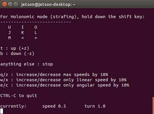
i(I)キーで前進、
u,o (U,O)キーで旋回、
j,l (J,L)キーで回転、
, (<) キーで後退、
k (k) キーで停止
車輪の形状を変えてみる
上記では車輪は単純化してCylinder を使っていましたが、これだと回転しているのが分かりません。
で、片側の車輪を形状が分かるdaeファイルで置き換えてみると回転しているのが確認できます。
こんな感じです。
Appendix
Gazebo 表示時の色指定
material Gazebo/Grey
material Gazebo/Gray : Gazebo/Grey
material Gazebo/DarkGrey
material Gazebo/DarkGray : Gazebo/DarkGrey
material Gazebo/White
material Gazebo/FlatBlack
material Gazebo/Black
material Gazebo/Red
material Gazebo/RedBright
material Gazebo/Green
material Gazebo/Blue
material Gazebo/SkyBlue
material Gazebo/Yellow
material Gazebo/ZincYellow
material Gazebo/DarkYellow
material Gazebo/Purple
material Gazebo/Turquoise
material Gazebo/Orange
material Gazebo/Indigo
material Gazebo/WhiteGlow : Gazebo/White
material Gazebo/RedGlow
material Gazebo/GreenGlow : Gazebo/Green
material Gazebo/BlueGlow : Gazebo/Blue
material Gazebo/YellowGlow : Gazebo/Yellow
material Gazebo/PurpleGlow : Gazebo/Purple
material Gazebo/TurquoiseGlow : Gazebo/Turquoise
material Gazebo/TurquoiseGlowOutline
material Gazebo/RedTransparentOverlay
material Gazebo/BlueTransparentOverlay
material Gazebo/GreenTransparentOverlay
material Gazebo/OrangeTransparentOverlay
material Gazebo/DarkOrangeTransparentOverlay
material Gazebo/RedTransparent
material Gazebo/GreenTransparent
material Gazebo/BlueTransparent
material Gazebo/DarkMagentaTransparent
material Gazebo/GreyTransparent
material Gazebo/BlackTransparent
material Gazebo/YellowTransparent
material Gazebo/LightOn
material Gazebo/LightOff
material Gazebo/LightBlueLaser
material Gazebo/BlueLaser
material Gazebo/OrangeTransparent

Leave a Reply