2軸Joystick モジュールをPico につないで、2軸のカメラマウントを動かしてみます。
開発環境はArduino IDE とMicroPython の2つを使ってみます。
構成
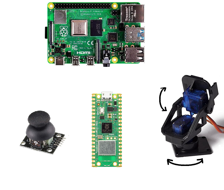
ラズパイ4 Model B はPico にファームウェアやプログラムを仕込むのに使います。
実際にカメラを使う場合は、processingなどでカメラ映像を表示するのに使います。
参照 Pi Pico でエッジAI を試してみる(1)カメラ
サーボモータようなデバイスはラズパイのようなSBCやPCより、Picoのようなマイコン(MCU)の方が高い精度で細かく制御できるようです。
こちらも参照ください。Pi Pico をI2C経由でラズパイ4Bから制御してみる(メモ)
用意するもの
GPIO について
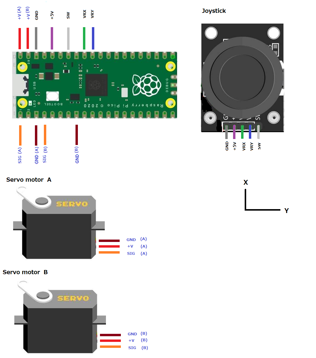
Pico ではADCが5つ使えて、そのうち3つ(GP26,27,28)がユーザーに開放されています。今回はそれを使います(VRX、VRY、SW)。
joystickについて以下もご参照
サーボモータには、GP0とGP2を使います。
Wiring (配線)
Arduino IDE
母艦(ラズパイ4)にArduino IDE をインストールしておきます。
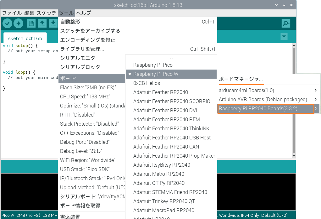
ボードマネージャーにEarle Philhower版をインストール」しておきます。
Arduino IDE でPi Pico Wの開発用にEarle Philhower版を使う
ツールー>ボードー>ボードマネージャー>Raspberry Pi RP2040 Board(3.3.2)ー>Raspberry Pi Pico W
ファイルー>新規ファイルで開いて書き込みます。
コードはこんな感じです。
Map関数の最大値、最小値はloop内のX_POS , Y_POS をシリアルモニターで確認しておいてください(表示が速すぎる場合はdelay を1000くらいにする)。
|
1 2 3 4 5 6 7 8 9 10 11 12 13 14 15 16 17 18 19 20 21 22 23 24 25 26 27 28 29 30 31 32 33 34 35 36 37 38 39 40 41 42 43 44 45 46 47 48 49 50 51 52 53 54 55 56 57 58 59 60 61 62 63 64 65 66 67 68 69 70 71 72 73 74 75 76 77 78 79 80 81 82 83 84 85 86 87 88 89 90 91 92 93 94 95 96 97 98 99 100 101 102 103 104 105 106 107 108 109 110 111 112 113 114 115 116 117 118 119 120 121 122 123 124 125 126 |
#include <Servo.h> Servo myservo_A; // create servo object to control a servo Servo myservo_B; int pos_A = 0; int pos_B = 0; int x_key = 26; // initializing ADC0 for storing the joystick’s x key value int y_key = 27; // initializing ADC1 for storing the joystick’s y key value int Push_Button = 28; // initializing digital pin 28 for joystick’s press to select button int x_pos = 0; // Declaring a variable for storing the value int y_pos = 0; // Declaring a variable for storing the value int btn_state = 0; // Declaring a variable for storing the value String js_state = ""; String prev_state = ""; void setup ( ) { pinMode(LED_BUILTIN, OUTPUT); Serial.begin (115200) ; // initializing serial communications at 115200 bps: pinMode ( x_key, INPUT ) ; // Selecting Arduino analog ADC0 pin as input pinMode ( y_key, INPUT ) ; // Selecting Arduino analog ADC1 pin as input pinMode (Push_Button, INPUT_PULLUP ) ; // This will activate pull-up resistor on the push-button pin myservo_A.attach(0, 544, 2400); myservo_B.attach(2, 544, 2400); } int Map(int x, int in_min, int in_max, int out_min, int out_max){ return (x - in_min) * (out_max - out_min) / (in_max - in_min) + out_min; } void ctrl_servo_A(String s){ if(s == "up"){ pos_A++; }else if(s == "down"){ pos_A--; } if (pos_A > 180) { pos_A = 180; } if (pos_A < 0) { pos_A = 0; } myservo_A.write(pos_A); } void ctrl_servo_B(String s){ if(s == "left"){ pos_B++; }else if(s == "right"){ pos_B--; } if (pos_B > 180) { pos_B = 180; } if (pos_B < 0) { pos_B = 0; } myservo_B.write(pos_B); } void loop ( ) { digitalWrite(LED_BUILTIN, HIGH); x_pos = analogRead (x_key) ; // Reading the value from ADC0 and storing in x_pos y_pos = analogRead (y_key) ; // Reading the value from ADC1 and storing in y_pos btn_state = digitalRead (Push_Button) ; // Reading the digital pin 28 is high or low Serial.print("X_POS = "); Serial.println(x_pos); Serial.print("Y_POS = "); Serial.println(y_pos); //X_POS , Y_POS の最大値、最小値をセット int adc_x = round(Map(x_pos,0,4095,0,18)); int adc_y = round(Map(y_pos,0,4095,0,18)); String js_state = "HOME"; if(btn_state == 1){ if((adc_x == 0)&&(adc_y == 13)){ js_state = "UP"; } if((adc_x == 18)&&(adc_y == 18)){ js_state = "DOWN"; } if((adc_x == 1)&&(adc_y == 18)){ js_state = "LEFT"; } if((adc_x == 0)&&(adc_y == 0)){ js_state = "RIGHT"; } }else if(btn_state == 0){ js_state = "PRESS"; } if(js_state == "UP"){ ctrl_servo_A("up"); }else if(js_state == "DOWN"){ ctrl_servo_A("down"); } if(js_state == "LEFT"){ ctrl_servo_B("left"); }else if(js_state == "RIGHT"){ ctrl_servo_B("right"); } if(js_state == "PRESS"){ myservo_A.write(90); myservo_B.write(90); } delay (10) ; // This will add delay between readings } |
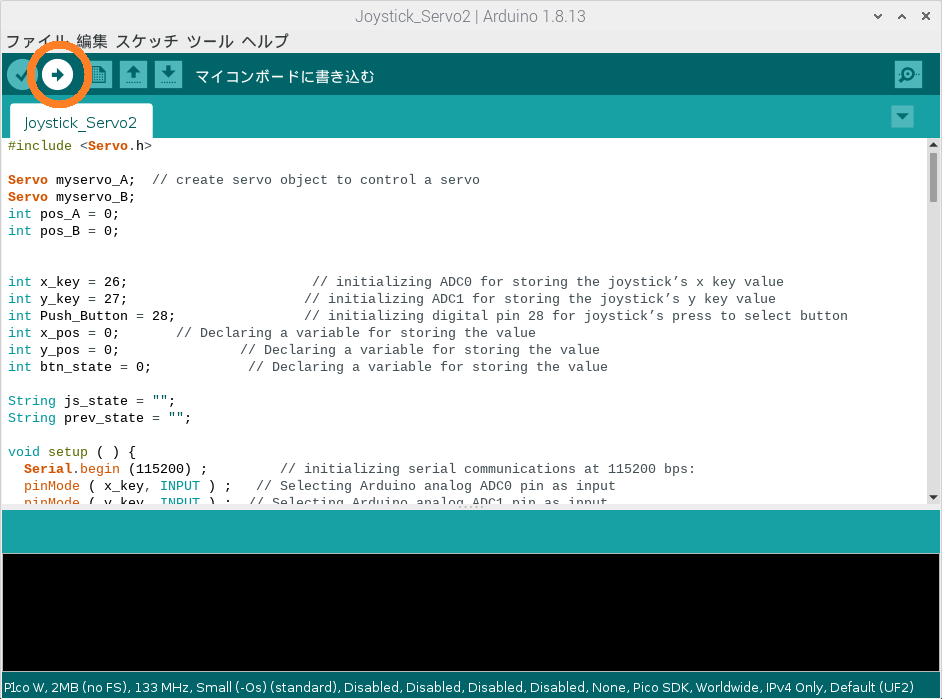
Pico をラズパイに接続して、マイコンボードに書き込むをクリック
MicroPython
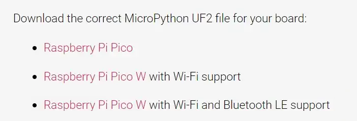
Pico W にMicropython用ファームウェアUF2をインストール
UF2 ファイルは、Raspberry Pi MicroPython ドキュメント ページにあります。
どれでもいいと思います。
ファイルをダウンロードしたら、BOOTSEL ボタンを押しながら、USB ケーブルを使用して Raspberry Pi Pico を母艦に接続します。 RPI-RP2 という名前の新しいドライブがファイル エクスプローラーに表示されます。 UF2 ファイルをこのドライブにドラッグ アンド ドロップ します。 完了すると、ドライブはファイル エクスプローラーから自動的に消えます。
Thonny IDE を使う
母艦であるラズパイにはThonny はプレインストールされています。
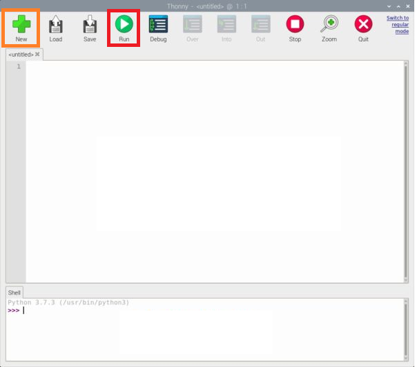
起動して新しいプロジェクトを開き(NEW)、以下の2つのコードをPico W に書き込み、main.pyを実行します(RUN)。
【servo.py】
|
1 2 3 4 5 6 7 8 9 10 11 12 13 14 15 16 17 18 19 20 21 22 23 24 25 26 27 28 29 30 31 32 33 34 35 36 37 38 39 40 41 42 43 44 45 46 47 48 49 50 51 52 53 54 55 56 57 58 59 60 61 62 63 64 65 66 67 68 |
from machine import Pin, PWM class Servo: """ A simple class for controlling a 9g servo with the Raspberry Pi Pico. Attributes: minVal: An integer denoting the minimum duty value for the servo motor. maxVal: An integer denoting the maximum duty value for the servo motor. """ def __init__(self, pin: int or Pin or PWM, minVal=2500, maxVal=7500): """ Creates a new Servo Object. args: pin (int or machine.Pin or machine.PWM): Either an integer denoting the number of the GPIO pin or an already constructed Pin or PWM object that is connected to the servo. minVal (int): Optional, denotes the minimum duty value to be used for this servo. maxVal (int): Optional, denotes the maximum duty value to be used for this servo. """ if isinstance(pin, int): pin = Pin(pin, Pin.OUT) if isinstance(pin, Pin): self.__pwm = PWM(pin) if isinstance(pin, PWM): self.__pwm = pin self.__pwm.freq(50) self.minVal = minVal self.maxVal = maxVal def deinit(self): """ Deinitializes the underlying PWM object. """ self.__pwm.deinit() def goto(self, value: int): """ Moves the servo to the specified position. args: value (int): The position to move to, represented by a value from 0 to 1024 (inclusive). """ if value < 0: value = 0 if value > 1024: value = 1024 delta = self.maxVal-self.minVal target = int(self.minVal + ((value / 1024) * delta)) self.__pwm.duty_u16(target) def middle(self): """ Moves the servo to the middle. """ self.goto(512) def free(self): """ Allows the servo to be moved freely. """ self.__pwm.duty_u16(0) |
【main.py】
|
1 2 3 4 5 6 7 8 9 10 11 12 13 14 15 16 17 18 19 20 21 22 23 24 25 26 27 28 29 30 31 32 33 34 35 36 37 38 39 40 41 42 43 44 45 46 47 48 49 50 51 52 53 54 55 56 57 58 59 60 61 62 63 64 65 66 67 68 69 70 71 72 73 74 75 76 77 78 79 80 81 82 83 84 85 86 87 88 89 90 91 92 93 94 95 96 97 |
import machine from machine import Pin,ADC from time import sleep from servo import Servo led = machine.Pin("LED", machine.Pin.OUT) s1 = Servo(0) s2 = Servo(2) VRX = ADC(0) # ADC0 multiplexing pin is GP26 VRY = ADC(1) # ADC1 multiplexing pin is GP27 SW = Pin(28, Pin.IN, Pin.PULL_UP) # ADC2 multiplexing pin is GP28 def Map(x, in_min, in_max, out_min, out_max): return (x - in_min) * (out_max - out_min) / (in_max - in_min) + out_min def servo_Angle(device,angle): if(device == "A"): s1.goto(round(Map(angle,0,180,0,1024))) elif(device == "B"): s2.goto(round(Map(angle,0,180,0,1024))) elif(device == "AB"): s1.goto(round(Map(angle,0,180,0,1024))) s2.goto(round(Map(angle,0,180,0,1024))) def direction(): global i i = 0 adc_X=round(Map(VRX.read_u16(),0,65535,0,255)) adc_Y=round(Map(VRY.read_u16(),0,65535,0,255)) Switch = SW.value() if adc_X <= 30: print("UP") i = 1 # Define up direction elif adc_X >= 255: print("DOWN") i = 2 # Define down direction elif adc_Y >= 255: print("LEFT") i = 3 # Define left direction elif adc_Y <= 30: print("RIGHT") i = 4 # Define right direction elif Switch == 0:#and adc_Y ==128: print("PRESS") i = 5 # Define Button pressed elif adc_X - 125 < 15 and adc_X - 125 > -15 and adc_Y -125 < 15 and adc_Y -125 > -15 and Switch == 1: print("HOME") i = 0 # Define home location def loop(): num = 90 device = "" while True: led.value(1) direction() # Call the direction judgment function #servo_Angle(num) sleep(0.01) #up if i == 1: #num = 0 num = num - 1 if num < 0: num = 0 device = "A" #down if i == 2: #num = 180 num = num + 1 if num > 180: num = 180 device = "A" #left if i == 3: num = num - 1 if num < 0: num = 0 device = "B" #right if i == 4: num = num + 1 if num > 180: num = 180 device = "B" # if i==5: num = 90 device = "AB" print(device) servo_Angle(device,num) if __name__ == '__main__': loop() # call the loop function |
サーボモーターを動かしてみましょう。
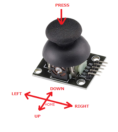
Joystick の動き(よく見るとちょっと変な気もしますが……..気にしない)
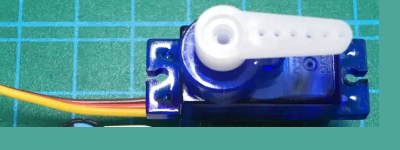
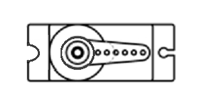
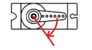
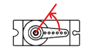
サーボモータの回転は以下のように制御されます。
ホームポジションをこう取った場合
PRESS
グッと押し込むとGNDに接続されて、ホーンはhomeポジションに戻ります。
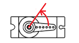
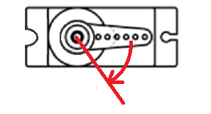
UP
ホーンは以下の位置まで瞬時に回転します。
DOWN
ホーンは以下の位置まで瞬時に回転します。
LEFT
ホーンは以下の位置までゆっくり回転します。速度はloop内のsleep()の引数で調整できます(0.01の値を大きくすればよりゆっくり回転します)。
RIGHT
ホーンは以下の位置までゆっくり回転します。速度はloop内のsleep()の引数で調整できます(0.01の値を大きくすればよりゆっくり回転します)。
カメラマウントを組み立ててみました
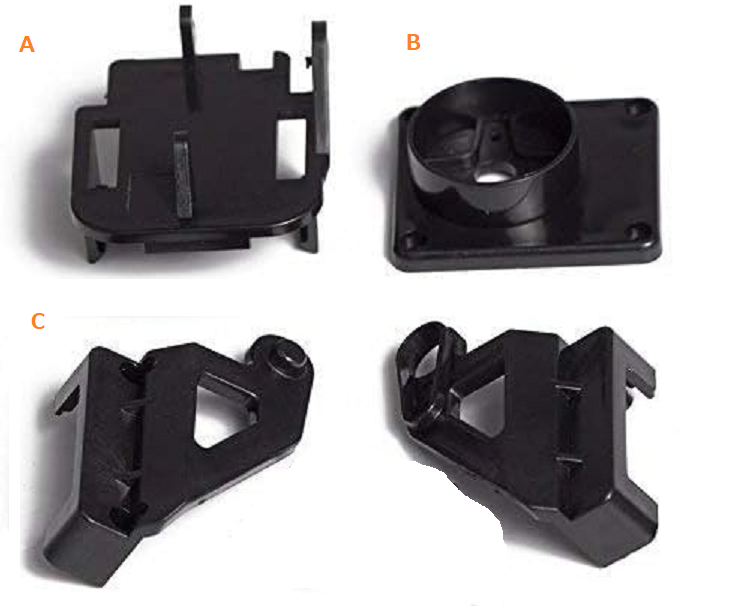
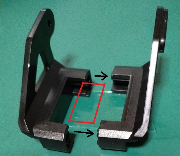
部品はこれだけです。
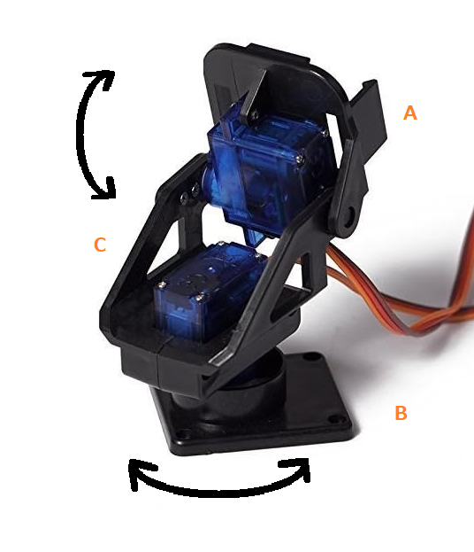
Aに上部モーターがセットされ、Bに下部モーターがセットされます。Cがそれをつなぐアームです。
全体像
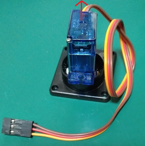
下部のモーターをセットして、上部のモーターを支えるアームを組みます。こんな感じです。
なかなかキツいですが、何とか入るサイズになっています。
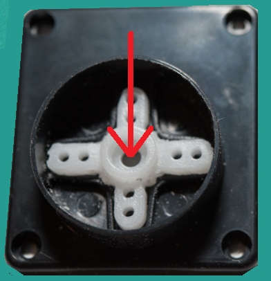
十字のホーンを切って削って押し込み、ここにモータをセットします。
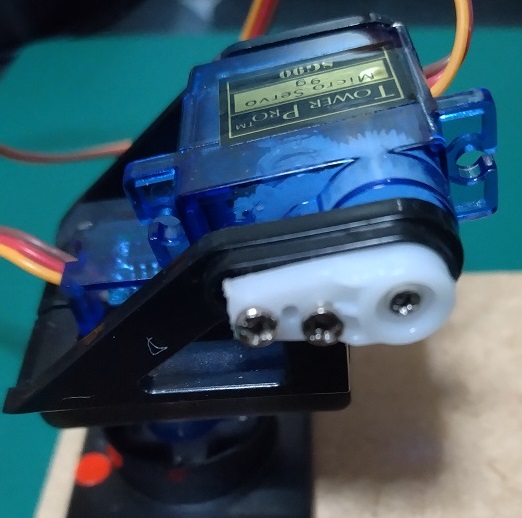
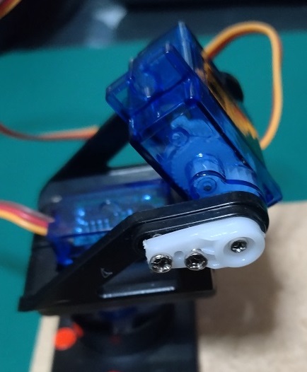
上部のモーターをセットする場合、事前に0度で回転させておいて、そのレベルでモーターを軸受けにセットします。0度の位置で上のモーターが下のモータに接触しないように調整しましょう。
上部モーターのホームポジション (90 度の位置)
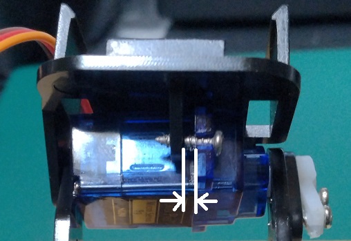
この時点で天井板をセットします。ただし、この製品、精度に問題があり、あまりきつくねじ止めすると、モーターの軸と軸受けがズレてしまい、回転時にズレのため軸に異常に負荷がかかり過電流が流れて発熱してモーターが死んでしまったことがあります。
ねじ止めも隙間を空けてゆるく止めておきます。
このsg-90も含めて低価格のサーボモーターはセーフティーがほぼ無いので、回転時に負荷がかかるのは禁止です。
動かしてみました。
ちなみに、動画の奥に見えているのがPico です。
最後にJoystickをpressして両方のモーターをホームポジションに戻しています。
Leave a Reply