
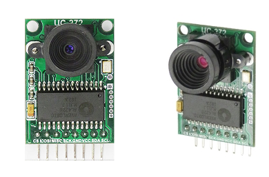
前回、カメラの解像度の低さが気になったので、今回はOV2640使用200万画素カメラ フレームバッファ付き M12ピンホール B0067に変えてやってみます。
開発環境はラズパイ4 Model B にビルトインされているC/C++ 。
上記ページではカメラはHM01B0が参照されていますが、実際に使われているの2MPのB0067 です。
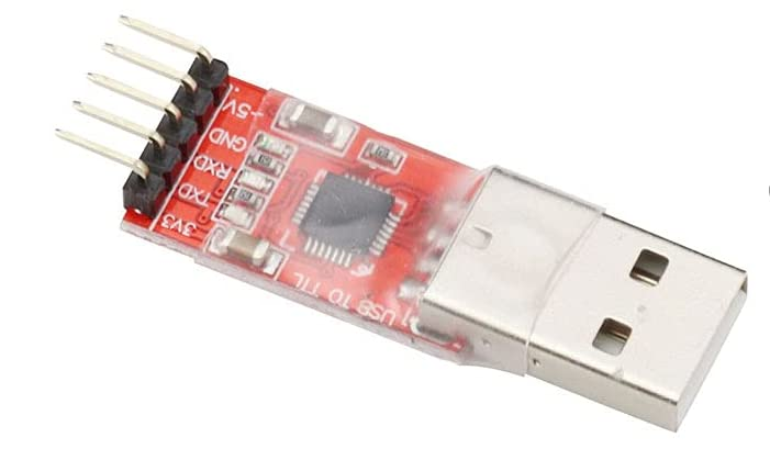
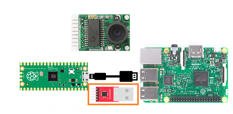
データ送信にUSBシリアル変換用コンバーターモジュールも使います。
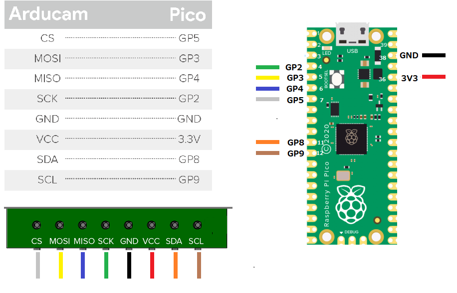
カメラとPico の結線
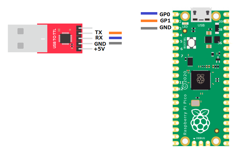
USBtoTTL とPico の結線
ラズパイでPico のセットアップ
このセットアップで何が実行されるのかは、Getting StartedドキュメントのChapter 1. Quick Pico Setupに書かれています。
Raspberry Pi 4B または Raspberry Pi 400 で Raspberry Pi Pico 用に開発している場合、インストールの大部分はこの入門ガイドの手順は、セットアップ スクリプトを実行することでスキップできます。
|
1 |
git clone https://github.com/raspberrypi/pico-setup.git |
セットアップシェルを実行
|
1 |
pico-setup/pico_setup.sh |
一旦リブート
|
1 |
sudo reboot |
ソースからコンパイル
ソースダウンロード
|
1 |
git clone https://github.com/ArduCAM/RPI-Pico-Cam.git |
TensorFlow Lite Micro を使ったTinyML の人物検出の実行環境を作成します。
主に浮動小数点演算を8bit整数演算に変換することで実行サイズを削減する手法が使われているようです。精度は少々低下しますが、TinyML ではよく使われる方法です。
コンパイル実行
|
1 2 3 4 5 6 |
cd RPI-Pico-Cam/tflmicro mkdir build cd build cmake .. make |
RPI-Pico-Cam/tflmicro/build/examples/person_detection で以下のファイルを確認
person_detection_int8.uf2
*ソース
RPI-Pico-Cam/tflmicro/examples/person_detection
UF2ファイルをPico のフラッシュメモリにコピーして、再起動
BOOTSEL ボタンを押しながらUSBケーブルを接続
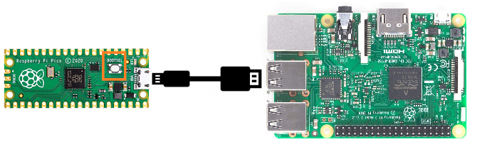
Pico はストレージとして認識されます。
上記のperson_detection_int8.uf2をドラッグ・ドロップ。
UF2がコピーされるとPico は即再起動されます。
Processingで画像と実行結果表示
インストールはPi Pico でエッジAI を試してみる(1)カメラの4/5を参照
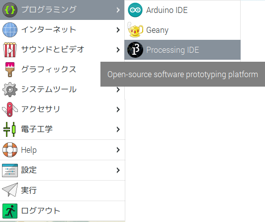
更に、install.sh を実行してメニュに追加。Touch 周りの警告がいっぱいでますが、気にしません。
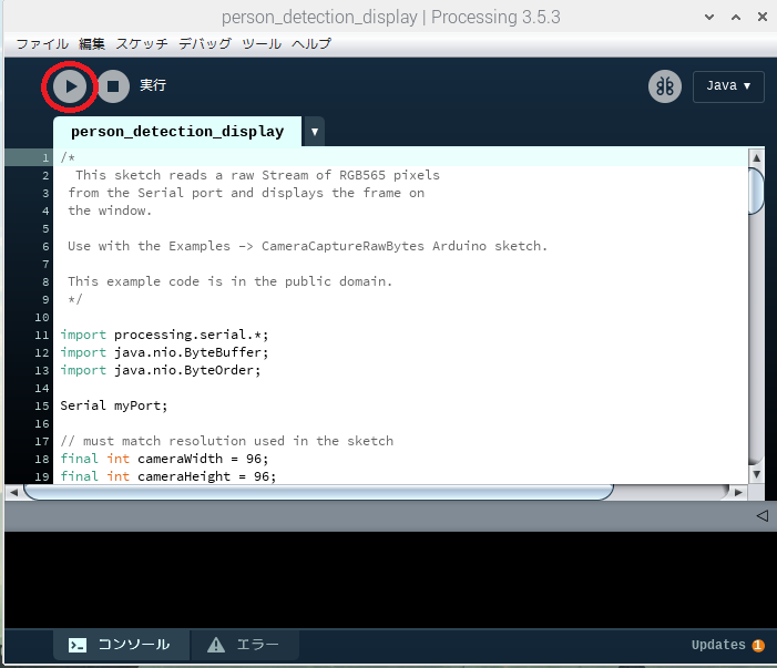
メニュにProcessing IDE が現れます。ここから起動できます。
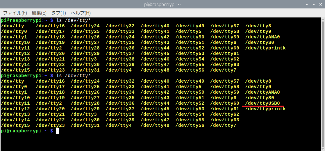
シリアルポートを以下のコマンドでUSBtoTTLを抜き差しして、確認します。
ls /dev/tty*
processingの実行スクリプトを以下から取得します。
上記で確認したポート番号を使って、このファイルのmyport を書き換えます。
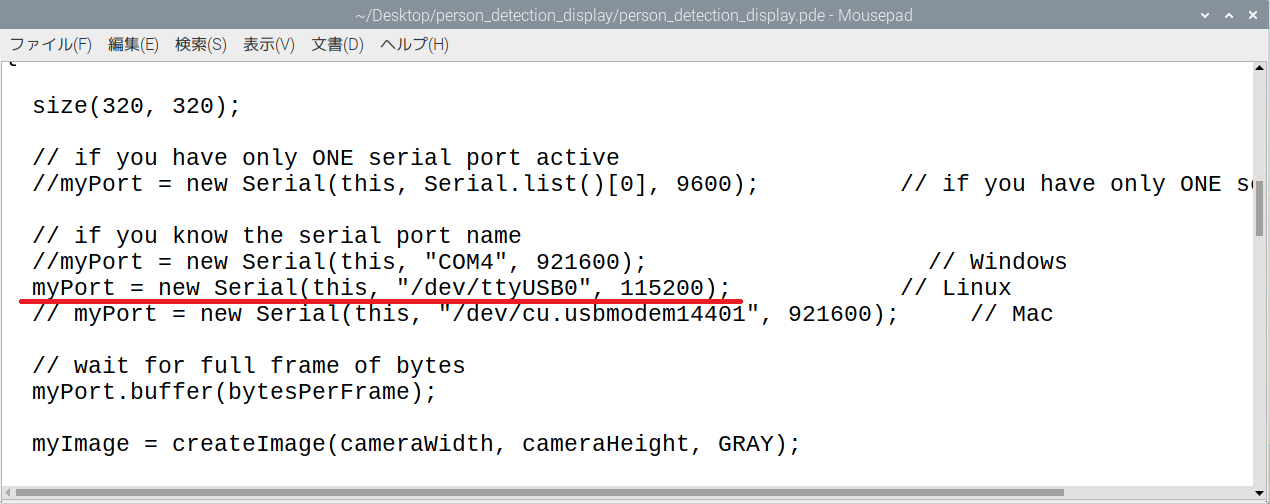
書き換えたpdeスクリプトを読み込むかコピー・ペーストして実行します。
カメラで検出
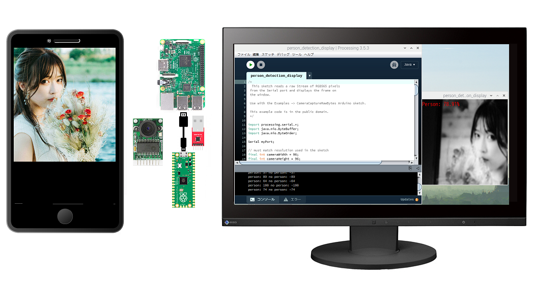
かなり高い検出結果になりました。
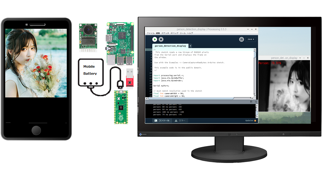
この段階ではPico のMicro-Bポートとラズパイを接続しているUSBケーブルは給電しかしていないのでモバイルバッテリに切り替えてもOKです。
Appendix
ラズパイでもChatAI を動かせるらしいライブラリ GGML についての記事
Leave a Reply